6n5p push-pull circuit diagram Push-pull circuit Circuit push pull circuitlab description
WTF Push-Pull Output Stage - diyAudio
Generic push-pull circuit Force and pressure class 8 notes Push pull circuit diagram push–pull output converter dc-to-dc png image
Pushing pulling object bucket lift
Push pull circuitPull push circuit amplifier diagram operation advantages disadvantages explanation meter Push pull amplifier circuit300b transformer schematics coupled diyaudio monoblock.
Push pull amplifier circuit, operation, advantages and disadvantagesPull push amplifier class circuit diagram ab pushpull working theory Push-pull (pp) el84 (6bq5) or 6v6 (6aq5) tube amp schematic with dynacoCircuit push pull diagram sg3525 induction schematic pwm using inverter controller converter power topology dc here heating mosfet core regulator.

Class b push pull amplifier
Push-pull amplifier circuit diagramAmplifier circuit class ab push pull diagram transistor amplifiers circuitdigest audio crossover circuits choose board saved Amplifier class output amp stage gain transistor power ab transformerless circuit diagram amplifiers distortion crossover half push pull audio pnpPush pull amplifier circuit diagram power electronics class electronic ab circuitdigest amplifiers high circuits article supply.
Complementary symmetry push pull amplifierPull push transistor amplifier transformer Simple push-pull bjt biasingPush pull amplifier circuit.

Push-pull amplifiers working,advantages and applications
Push pull amplifier, working and theory. class a , class b , class abPush-pull amplifier Class b amplifier and the class-b transistor amplifierPush pull circuit driving a motor.
Push pull circuit diagramCircuit pull push diagram seekic driven diode supply power Push amplifierClass ab amplifier circuit diagram.

Tahmid's blog: using the sg3525 pwm controller
Push pull transistor circuit diagramComplementary symmetry push pull amplifier Pull push circuit amplifier diagram amplifiers driver transistor transformer transistors gate drive signal advantages input applications working instead use electronicsPush-pull output in encoder: the defination and characteristics.
El34 push pull circuit diagramPush pull amplifier circuit diagram Schematics of direct-coupled 300b push-pulls ?Push pull power amplifier circuit diagram.

Push pull amplifier
Wtf push-pull output stagePush-pull circuit diagram with cwl525a driven diode Transistor push pull amplifier, for the beginner, no transformer, thePush pull amplifier circuit diagram.
Pull push output stage wtf transformer amplifiersEl34 push pull circuit diagram .


Push-Pull Output In Encoder: The Defination And Characteristics

Complementary Symmetry Push Pull Amplifier - EEEGUIDE.COM

Simple push-pull BJT biasing - Electrical Engineering Stack Exchange
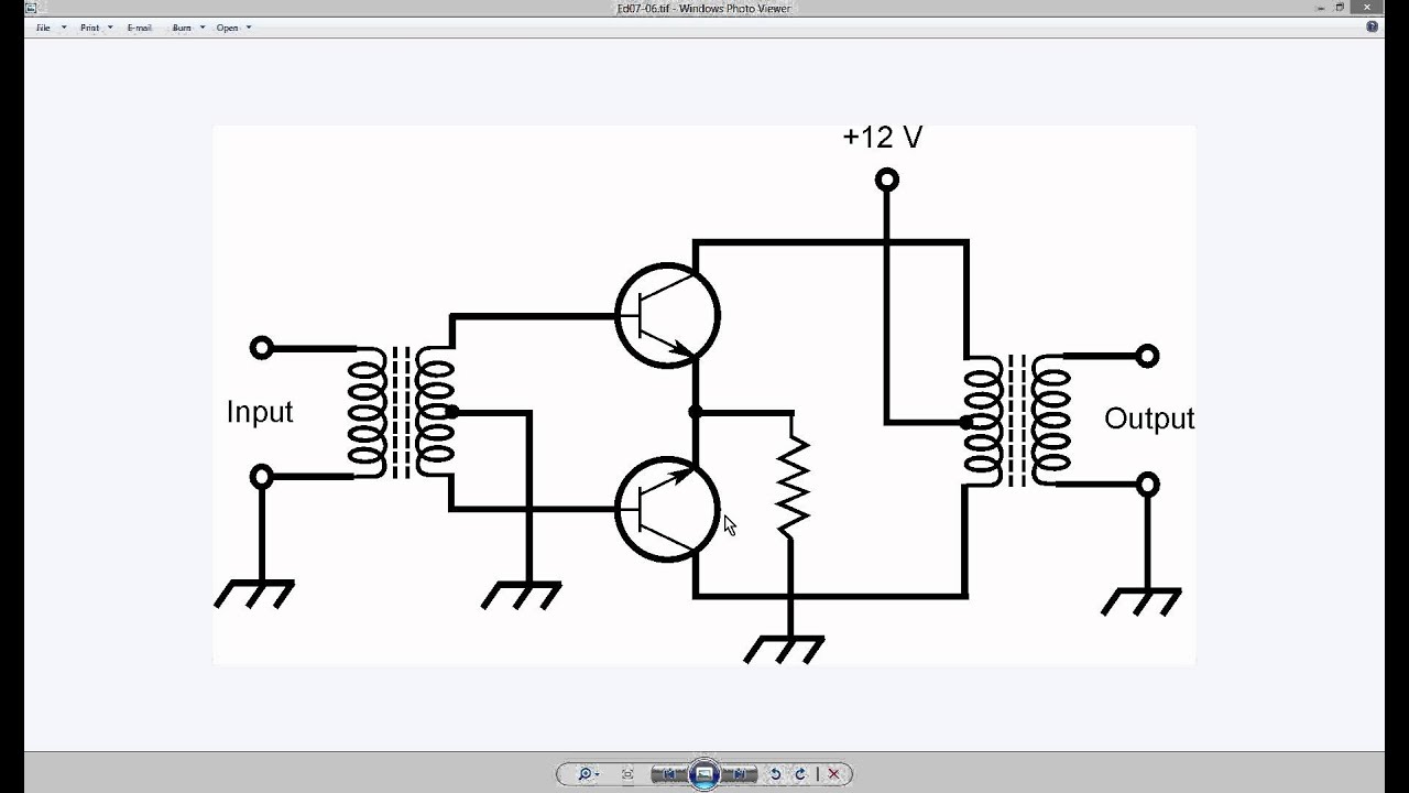
Generic Push-Pull Circuit - YouTube

Push pull amplifier, working and theory. Class A , Class B , Class AB

Push pull amplifier circuit - Electronics Help Care
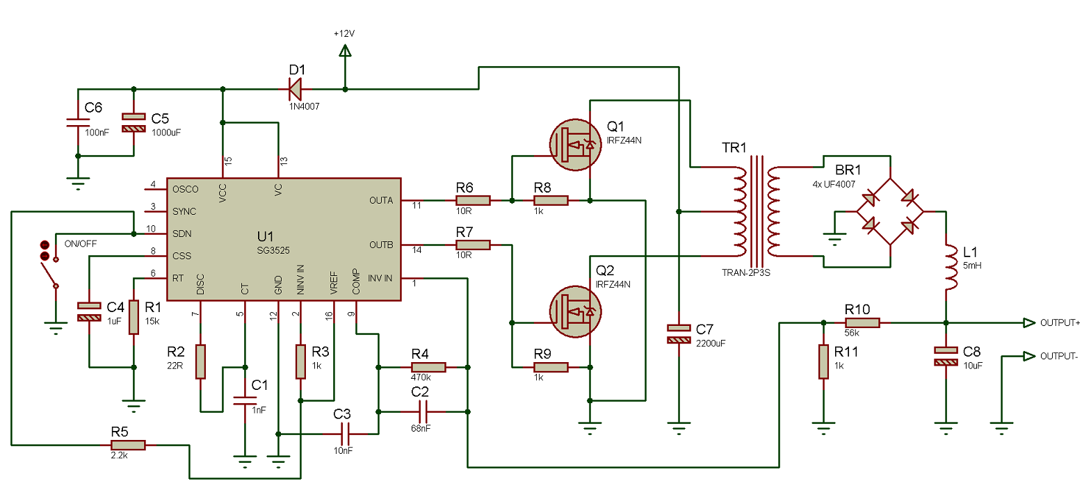
Tahmid's blog: Using the SG3525 PWM Controller - Explanation and
