Pwm wiring diagram Pwm wiring diagram 4 pin pwm fan circuit diagram
PWM diagram | Home Model Engine Machinist Forum
Schematic wiring diagram Hydraulics diverter summit grapple tilt Motor control circuit with timer
Pwm diagram
Ec fan pwm wiring diagram faePwm fan diagram wiring pump fans cpu control cooler motherboard water does work wire ec power plug rgb controlling pc Pwm controller circuit diagramCpu cooler.
Pwm noise pulse modulation width current high wiring grounding instrument emi field controller driver signals voltage instrumentation diagram ground wireSolenoid clutch ishift oe servo Pwm diagramLaptop wiring diagram 12v solar diagrams offgridcabin mk yugteatr.

Pwm fan wiring diagram
Ec fan pwm wiring diagramPwm duty cycle works Pwm skema 4s lipoPwm diagram.
Pwm fan diagram wiring pump fans cpu cooler control speed motherboard case ec water wire power rgb plug controlling pcPwm f-idle valve Volvo ishift clutch servo solenoid control valve (volvo oe)Pwm wiring diagram.

How pwm and duty cycle works
Pwm 555 audio circuit amplifier timer transformer electronicsforuMechanic page: how to wiring pwm module and why? Pwm v2.1 plans, parts list, board layout and schematic3 wire computer fan wiring diagram.
Pwm wiring diagramHigh voltage power supply based pwm ic tl494 Pwm wire module wiring mechanic understand four easy little hasPreventing emi and reducing noise from high current pwm signals.

Circuit pwm signal 12v 5v current schematics microcontroller diagrams amplification convert higher mosfets controlling fertilizer duty drop heavy motor drive
Pwm emi pulse modulation grounding shielded actuator signals reduce reducing proper prevent logicCircuit schematics Pwm schematic circuit nrg alt v2 hho layout plans parts list board electrolysis current 150a saved innen mentveWhat is a third function valve kit, and what are the benefits of one?.
Mechanic page: april 2020What is pwm and how does it work? 555 audio pwm apmlifierMechanic page: how to wiring pwm module and why?.

4 pin pwm fan wiring diagram
Pwm mechanic module confusing connect why need they like3 wire solenoid valve wiring diagram Pwm wiring diagramPwm dimmer wiring 24v tl494 triac pulse modulation eleccircuit ne555 circuits transistors 20a amplifier saving darlington potentiometer 10k источник статьи.
Pwm valveVoltage tl494 pwm ic amplifier circuits transformer charger rangkaian skema regulator Pwm module why wiring mechanic confusing connect need they like.


How PWM and Duty Cycle Works - YouTube

Motor Control Circuit With Timer
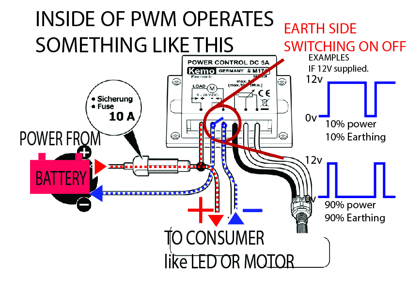
Mechanic page: HOW TO WIRING PWM MODULE AND WHY?

What is a third function valve kit, and what are the benefits of one?

PWM v2.1 plans, parts list, board layout and schematic

Pwm Wiring Diagram - What Is Pwm And How Does It Work Ekwb Com
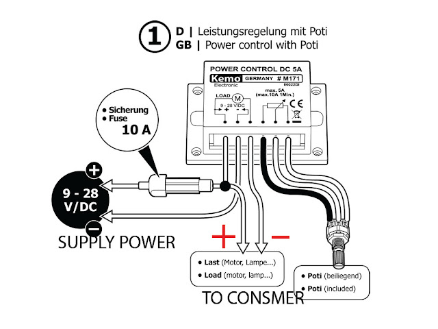
Mechanic page: HOW TO WIRING PWM MODULE AND WHY?
